The QHY-GPSBOX is a compact camera accessory that provides high-precision GPS hardware time scales allowing some QHYCCD cameras to obtain accurate time information of the camera's exposure time. In addition, this information is returned to the camera internally and added to the image data after the start of one frame of the image. GPS timing information and image information are therefore completely consistent. No confusion is created due to transmission, buffering or other reasons. It is very convenient to use and read.
The QHY-GPSBOX has a built-in GNSS module and can currently provide both pure GPS operation and GPS/Beidou dual-mode operation. The latter can be set to work in GPS mode or Beidou mode through software. The GPSBOX also contains a local 10MHz voltage controlled crystal oscillator (VCXO) that provides an internal 0.1us resolution timing clock. At the same time, the timing clock is reset by the PPS model of the GNSS module. Therefore, the clock and the GNSS system’s second start time are strictly aligned, and the error is within a range of 20ns to 100ns.
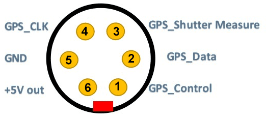
QHY-GPSBOX and camera are connected by 6-pin aviation plug. Contains the following signals:
| Pin |
Function |
Description |
| 1 |
Gnd |
|
| 2 |
Communication clock.
Level 1.8V or 2.5V |
Output to GPSBOX by camera.
Frequency <= 40MHz |
| 3 |
Communication data.
Level 1.8V or 2.5V |
Single-wire serial communication using
synchronous feature head + data mode. |
| 4 |
Configuration Data
Level 1.8V or 2.5V |
Beidou / GPS selection |
| 5 |
Measure the waveform
Level 1.8V or 2.5V |
The camera measures the waveform based on the electronic shutter generated by the image sensor drive and outputs it to the GPSBOX |
| 6 |
+ 5V |
Camera output power supply |
Note that when choosing a camera, you must specify the special version with a GPS socket. The socket used in the standard version is a 5-core aviation socket. When the camera is working, an electronic shutter measurement waveform is generated every frame. The waveform is output to the GPSBOX. After the GPSBOX performs high-precision time measurement, it outputs a serial header data and sends it back to the camera. The camera records these data after the frame header of each frame (replacing some pixel values in the first few lines)
QHYGPS has a perfect fault tolerance mechanism. It can deal with the situation when the PPS signal is lost. If the PPS signal is lost, after 50.0us, an internal second step will be used. And this information will be recorded. For timing information without a PPS signal, a cumulative timing error of 50us per second will be generated. When the PPS signal is restored, the PPS signal will be used again to reset the internal timer. Therefore, it has GPS timing accuracy after recovery and will not accumulate previous errors.
The QHYGPS will also output a GPS measurement value of an internal 10MHz clock every second. This measurement value can be used to accurately calibrate the frequency of the internal 10MHz crystal oscillator in later software to avoid an internal 10MHz crystal oscillator error and temperature drift.
Currently ONLY the following models have 6-pin aviation plug which supports GPSBOX (without further modification).
QHY600 Pro
QHY268Pro
QHY4040
QHY4040Pro
QHY6060
QHY42Pro
QHY411
QHY461
Other models don’t have a 6-pin plug but can be modified to be compatible with the QHY-GPSBOX. Please contact QHYCCD for such requirments.
GPXBOX-QHY600Pro High Precise Time Measurement
QHY600 Professional version has 5pin/6pin GPIO socket. Which can output the Vsync , Hsync signal for meassurement. It can connect with the QHY-GPSBOX to do directly time test and encode the meassured information into the image.
This document will introcude how to get the precise time meassurement of it.
Due to the rolling shutter of the QHY600 cmos sensor. The camera can not output a signal to indicate the global exposure starting and global expsoure ending. The signal for meassurement is Vsync. Vsync is apporx the time that one frame starting to readout. So it is very close to the exposure end time of row 0. The pulse width of Vsync is about 0.4us.
Rolling Shutter Timing
For rolling shutter. It is row based exposure. Normally speaking the end of the exposure is happend at the time when one row begin to readout. And the start of the exposure is controlled by register and the unit is row period.
exposure time = n * row period
If we get to know the end of exposure time of row 0. We get to know the start exposure time is
exposure start time row 0 = exposure end time row 0 – exposure time 0
And we can get to know other rows start exposure and end exposure :
exposure start time row 1 = exposure start time row 0 + row period
exposure start time row 2 = exposure start time row 0 + 2 * row period
……
exposure end time row 1 = exposure end time row 0 + row period
exposure end time row 2 = exposure end time row 0 + 2 * row period
……
fig.1 The timing graph when exposure time is one row period (short exposure mode)
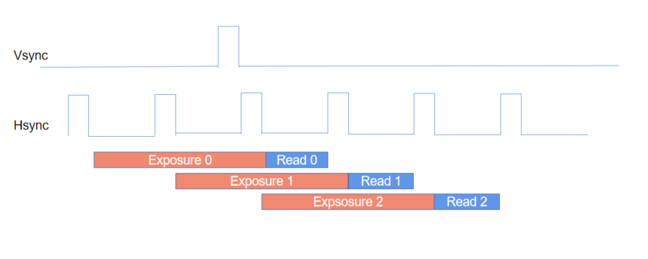
fig.2 The timing graph when exposure time is two row period (short exposure mode)
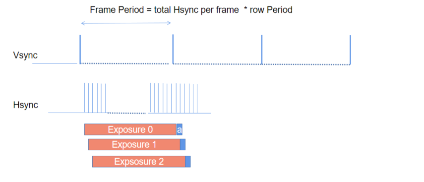
fig.3 The timing graph in long exposure mode. long exposure is done by increase the hsync number between two vsync. So the exposure time = frame period .
For precise time meassurement. Once we get the time of end of exposure time of row 0. We can get all other row’s end exposure time and start exposure time.
If the object is a point source. We can get to know its position (X,Y) in the image. Then we can use the exposure start and end time of this row for the object’s exposure start/end time.
Get to know the Vsync time to the first row end time
Because the cmos sensor does not output certain row’s end exposure time , like the row 0’s end exposure time. And also , since we need to use the (X,Y)position to calculate the object. We need to know the relationship that the row on the image to the exposure time . For example, the row 0 on image may not the row 0 in the fig.1,2,3. Because the sensor has the optic black rows.
In order to meassure the vsync signal to the end of exposure time of row 0 in the image. We need to use the LED calibration method to do it.
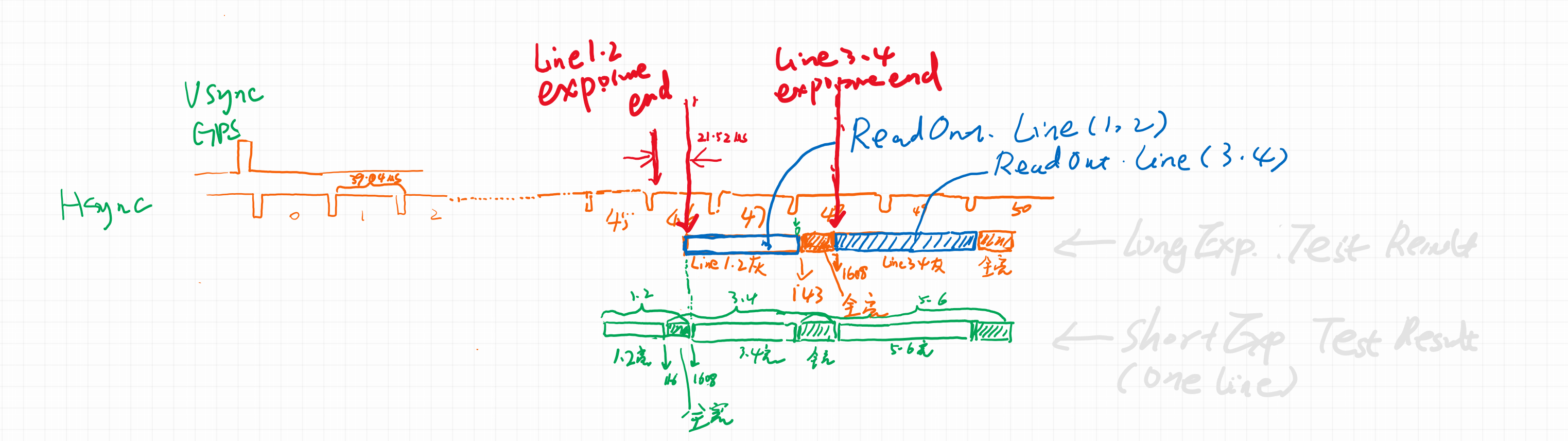
We use the LED method to test the timing and found the the camera is exposured with two rows together. And for default resolution when capture with SharpCAP, USB_TRAFFIC=0. Line1 and Line2 ends of exposure in the HSYNC=46. And the position to the falling edge of hync is 21.52us. So we can get to know:
T (end exposure, line1&2) = GPS position + 46 * LinePeriod + 21.52us.
When in ROI mode, it is best to redo the LED calibration to get accurate value. QHYCCD can supply the LED calibration tools for calibrate it.
Important: For 2CMS mode , The exposure is with one rows, not two rows togehter. And the “46” and the “21.52us” will not the same.
FAQ
(1)What parameter will effect the LinePeriod and how to get to know the LinePeriod.
USB_TRAFFIC, 8bit/16bit setting will change it. You can use osciliscope to meassure the HSYNC signal to get to know the LinePeriod. In QHYCCD SDK there is a API also can return it. But it is best to use the osciliscope to double check it.
uint32_t STDCALL GetQHYCCDPreciseExposureInfo(qhyccd_handle *h,uint32_t *PixelPeriod_ps,uint32_t *LinePeriod_ns,uint32_t *FramePeriod_us,uint32_t *ClocksPerLine, uint32_t *LinesPerFrame,uint32_t *ActualExposureTime,uint8_t *isLongExposureMode
(2)What parameter will effect the “46” in above text?
The ROI , LiveFrame/SingleFrame, the 2CMS/non 2CMS will effect it. It is best to use LED calibrate method to test it to confirm the detail timing.


 In Stock
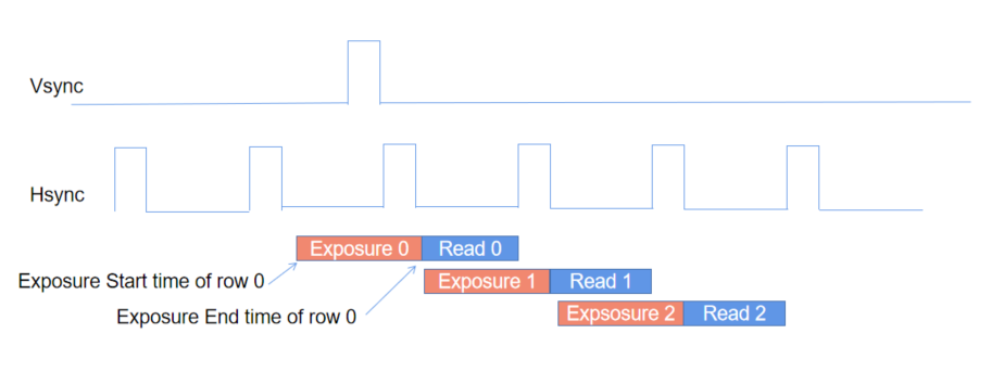

