QHY
QHY174GPS
- Regular price
- $ 1,239.00
- Sale price
- $ 1,239.00
- Unit price
- per
This item is out of stock but you can place an order now and we’ll ship when it becomes available.
 In Stock
| Model | QHY174GPS |
| COMS Sensor | SONY IMX174 CMOS |
| Pixel Size | 5.86um*5.86um |
| Effective Pixel Area | 1920*1200 |
| Effective Pixels | 2mega |
| Effective Image Area | 11.25mm*7.03mm |
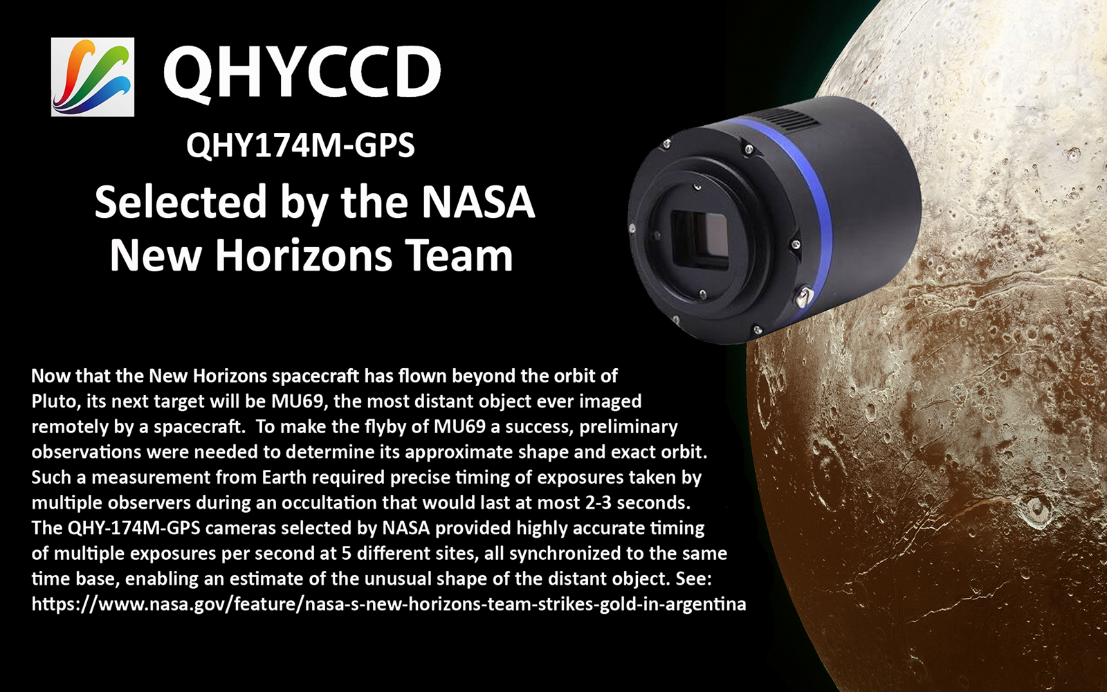 “This effort, spanning six months, three spacecraft, 24 portable ground-based telescopes, and NASA’s SOFIA airborne observatory was the most challenging stellar occultation in the history of astronomy, but we did it!” said Alan Stern, New Horizons principal investigator from SwRI.
http://www.boulder.swri.edu/MU69_occ/july17.html
https://www.nasa.gov/feature/new-horizons-deploys-global-team-for-rare-look-at-next-flyby-target
https://www.nasa.gov/feature/nasa-s-new-horizons-team-strikes-gold-in-argentina
The QHY174GPS camera uses the 1/1.2-inch SONY IMX174 CMOS sensor with global shutter, 5.86um pixels,138FPS@1920*1200, high QE of 78%, and low read noise of 3-5e-. It is useful for imaging occultations, eclipses, meteors, and other scientific imaging requiring a highly precise recording of the time and location of the observation on every frame.
The QHY174GPS has a unique built-in GPS module that can sync with the atomic clock signals received from GPS satellites. The QHY174GPS can record the start and end of exposure time with 1us precision anywhere on earth. The QHY174GPS was selected by the NASA New Horizons Team to successfully captured the MU69 occultation in the Summer of 2017. The QHY174M-GPS has dual stage TE cooling to -45C below ambient with full anti-moisture control including heated optical window and removable desiccant plug for the sensor chamber. The QHY174 also has an anti-amp glow function. It can reduce the IMX174 sensor’s amplifier glow significantly in long exposures.
The QHY174M-GPS records the global shutter exposure starting and ending time with microsecond precision. Two QHY174 cameras, for example, each located anywhere in the world, can have the same time base, accurate to microseconds. In order to guarantee the starting and ending time of the exposure, the QHY174 has a built-in LED pulse calibration circuit precise to 1 microsecond.
 Unlike the rolling shutter technology used in most CMOS cameras, a global shutter guarantees that the exposure time for the whole image area is uniform, beginning and ending at exactly the same time. This type of shutter is ideal for high precision applications. For high speed moving object and the atmospheric agitation the global shutter can generate undisborted imaging and realizes high picture quality.
Master mode: In Master Mode, the camera is free running and the internal 10MHz GPS synced clock will measure and record the shutter’s opening and closing time.
Slave mode: In Slave Mode you can input a target start time and the interval period for two frames. For example: You want three cameras in different locations (maybe thousands of kilometers apart) to start an exposure at 2016.3.9.UTC 14:00:00.000000 and then to continue with exposures at the interval time of 0.100000 sec. After you input these value, all the three cameras will wait until this time and then simultaneously start video recording, e.g.:
2016.3.9 UTC 14:00:00.000033
2016.3.9 UTC 14:00:00.100033
2016.3.9 UTC 14:00:00.200033
2016.3.9 UTC 14:00:00.300033
(The 0.00033 is a global delay of the CMOS shutter).
The time stamp and other GPS information is embedded into the image. The software decodes it in real time and displays the information on left. Since the data is embedded, it will never be lost so long as you keep the original image.
| Model | QHY174GPS |
| COMS Sensor | SONY IMX174 CMOS |
| Pixel Size | 5.86um*5.86um |
| Effective Pixel Area | 1920*1200 |
| Effective Pixels | 2mega |
| Effective Image Area | 11.25mm*7.03mm |
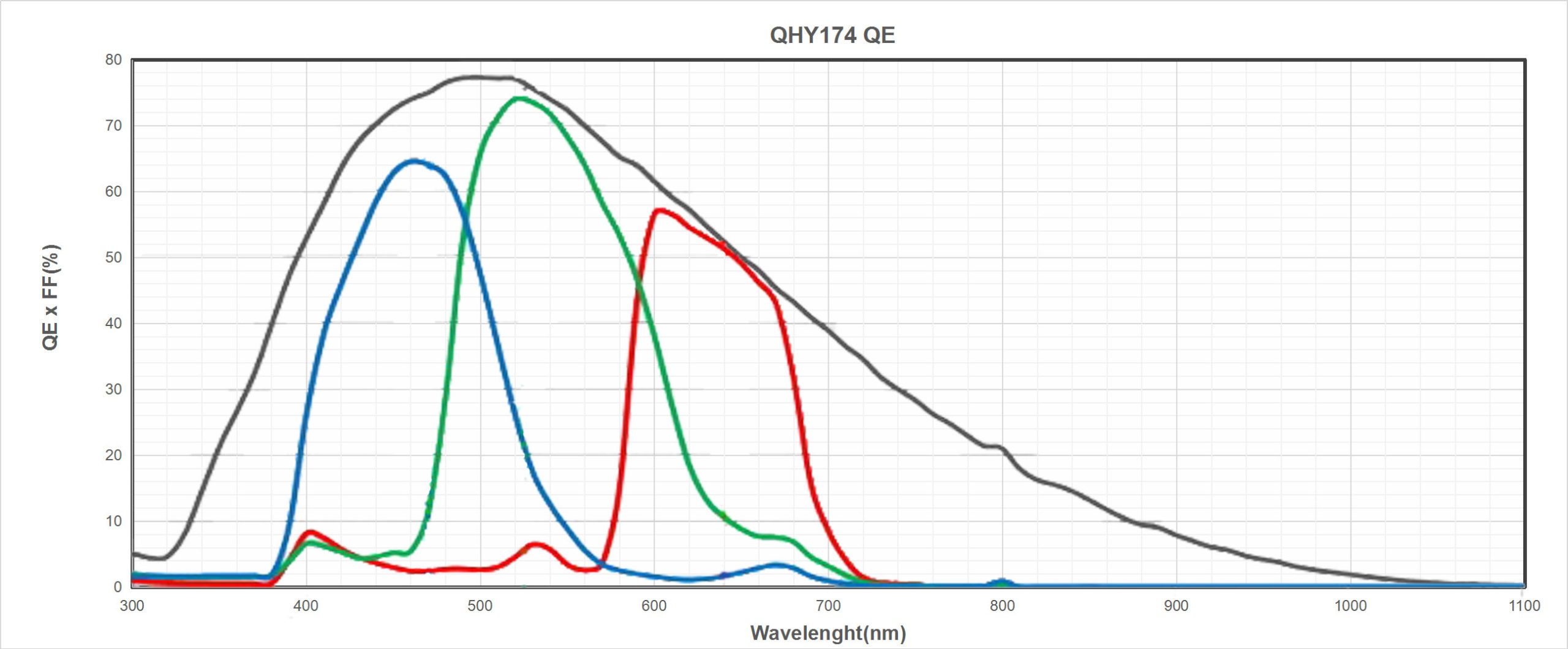
| QE | 78% |
| Fullwell | >32ke- |
| AD Sample Depth | 12/10bit (output as 16bit and 8bit) |
| Sensor Size | Typical 1/1.2 inch |
| Full Frame Rate and ROI Frame Rate | 138FPS@1936×1216
260FPS@960×600 490FPS@480×300 *Note:QHYCCD has optimized the cmos drive frequency and limit the max frame rate. The CMOS sensor may not work under the max frequency to ensure the better noise performance. If you need the customized higher frame rate version, please contact QHYCCD. |
| ROI Support | Yes. Any Area ROI |
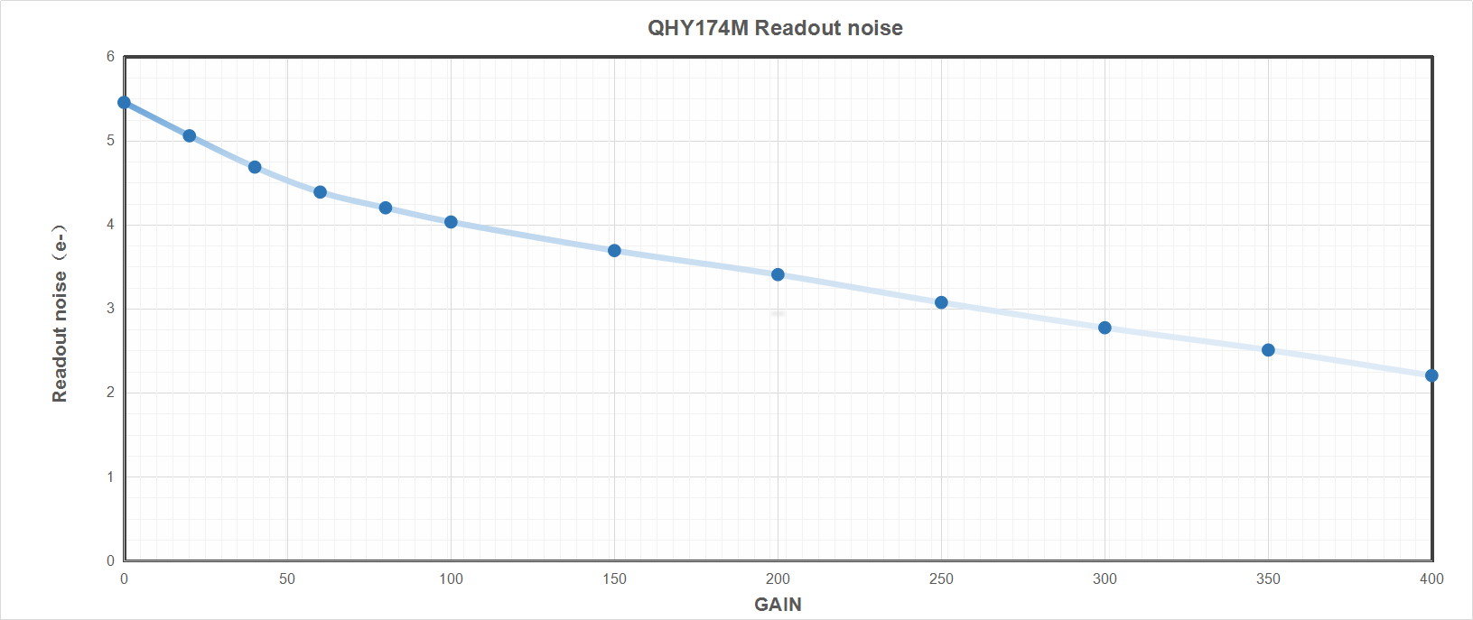
| Readout Noise | 5.3e-@Gain0% 2.8e-@Gain60% 1.6e-@Gain100% |
| Exposure Time Range | 5us-900sec |
| Binning | 1×1,2×2 |
| Anti-Glow Control | Yes (Reduces amplifier glow significantly) |
| Shutter Type | Electric Global Shutter |
| Computer Interface | USB3.0 Super Speed |
| Non-volatile memory / On camera storage | Build-in total 512Kbytes Flash Memory. 100Kbytes user-accessible space for stellar ROI frames for analysis of exoplanet investigation, occultations, atmospheric seeing measurement, focus , optic analysis etc. Support 100*100 image x 10rames 50*50 image x40frames. 25*25 image x160frames 10*10 image * 1000 frames (total frame numbers is based on 8bit image) |
| Cooling System | Dual Stage TEC cooler(-40C below ambient),
(Test temperature +20°) Temperature Regulated |
| Anti-Dew Control | Connector for removable silicon gel tube
Heater board for CMOS chamber optical window |
| Telescope Interface | M42/0.75 / 2inch faster installer. Optional C-mount adapter |
| Optic Window Type | Mono Version: AR+AR High Quality Multi-Layer Anti-Reflection Coating
Color Version: IR cut coating |
| Guide Port | 6PIN RJ11 Guide Port |
| Color Wheel Port | 4PIN QHYCFW Socket |
| Back Focal Length | 17.5mm |
| Weigth | 450g |
| GPS version, Time-Stamp Precision | 1 micro-second of the GPS UTC clock |
| Reference Price | QHY174M-GPS USD1239 w/TE Cooling |

Click to Read QHY174M-GPS On-Line Technology Document
Click to Read QHY174GPS Design PDF File

The camera requires an input voltage between 11V and 13.8V. If the input voltage is too low the camera will stop functioning or it may reboot when the TEC power percent is high, causing a drain on the power. Therefore, please make sure the input voltage arrived to the camera is adequate. 12V is the best but please note that a 12V cable that is very long or a cable with small conductor wire may exhibit enough resistance to cause a voltage drop between the power supply and the camera. The formular is: V(drop) = I * R (cable). It is advised that a very long 12V power cable not be used. It is better to place the 12V AC adapter closer to the camera.
First connect the 12V power supply, then connect the camera to your computer via the USB3.0 cable. Make sure the camera is plugged in before connecting the camera to the computer, otherwise the camera will not be recognized. When you connect the camera for the first time, the system discovers the new device and looks for drivers for it. You can skip the online search step by clicking “Skip obtaining the driver software from Windows Update” and the computer will automatically find the driver locally and install it. If we take the 5IIISeries driver as an example (shown below), after the driver software is successfully installed, you will see QHY5IIISeries_IO in the device manager.
Please note that the input voltage cannot be lower than 11.5v, otherwise the device will be unable to work normally.
All-in-one Pack supports most QHYCCD models only except PoleMaster and several discontinued CCD cameras.
Download Page: https://www.qhyccd.com/download/
Video Tutorial: https://www.youtube.com/embed/mZDxIK0GZRc?start=1
- Since most of the contents of All-in-one package are plug-ins that support third-party software, the third-party capturing software that you want to use must be installed before the All-in-one package. Otherwise the program will report an error.
-
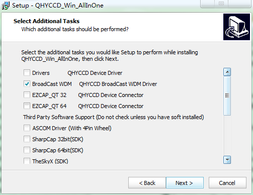
ALL-IN-ONE Pack contains:
- System Driver, which is necessary for the camera operation and must be installed.
- WDM Broadcast Driver, which can provide a live signal to Obs and other live software, you can install it if you have such needs like opeing a live show.
- EZCAP_QT , which is developed by QHYCCD and can be used in QHY devices tests, and management of updates. So even if you won’t use EZCAP_QT for capturing, we suggest you install it.
- Ascom driver, which is necessary for the camera used in Ascom (the latest version of Ascom is 6.6).
- The two sorts of Ascom CFW Drivers correspond to two methods of controling the filter wheel: USB control and camera serial control. It is recommended that both drivers should be installed if you have a filter wheel.
- CP210X_VCP is a serial driver. Some computers come with the driver, but the computer without the driver may be failed of controling the filter wheel.
- SDKs for Third-party Software: Just pick and install the corresponding SDK according to the software you want to use. Don’t forget to check whether the software you are using is 32-bit or 64-bit and select the right SDKs.
- SHARPCAP is also included in the pack, you can choose 32-bit or 64-bit to install. This is authorized by SHARPCAP.
- QT LIB is a plug-in to ensure that 64-bit software can exeuate normally on some computers with poor compatibility.
- Difference between Stable version and Beta Version: Beta version is the latest version, which gives priority to support for the latest products (the stable version may not be compatible with those yet), and has some of the latest optimized ,but experimental features. The stable version is older than the beta version but more stable, so it is recommended for beginners who are not using the latest products.
- Don’t let the camera connect to the computer during the All-in-one pack installation process; connect it to the computer after all the installation is complete.
Before using software, make sure you have connected the cooling camera to the 12V power supply and connected it to the computer with a USB3.0 data cable. If it’s an uncooled camera, 12V power is not needed.
Note: We recommend 64-bit Software if possible, like SharpCAP x64 , N.I.N.A x64. etc., especially when you’re using 16bit cameras.
EZCAP_QT is software developed by QHYCCD. This software has basic capture functions for QHYCCD deep sky cameras.
Run EZCAP_QT. Click “Connect” in Menu -> Camera. If the camera is successfully connected, the title line of EZCAP_QT will display the camera firmware version and the camera ID as shown below.
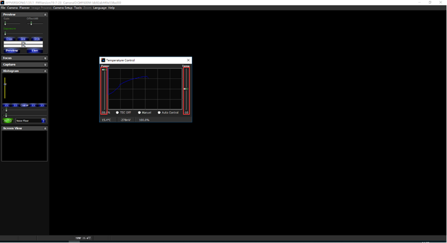
Click “Temperature Control” in “Camera Settings” to set the temperature of the CMOS sensor. You can turn on “Auto” to set the target temperature. For example, here we set the target temperature to -10C. The temperature of the CMOS sensor will drop quickly to this temperature (approximately 2-3 minutes). If you want to turn off cooling, you can choose Stop. If you just want to set the TEC power but not the temperature. You can select “Manual” and then set the percentage of the TEC power.
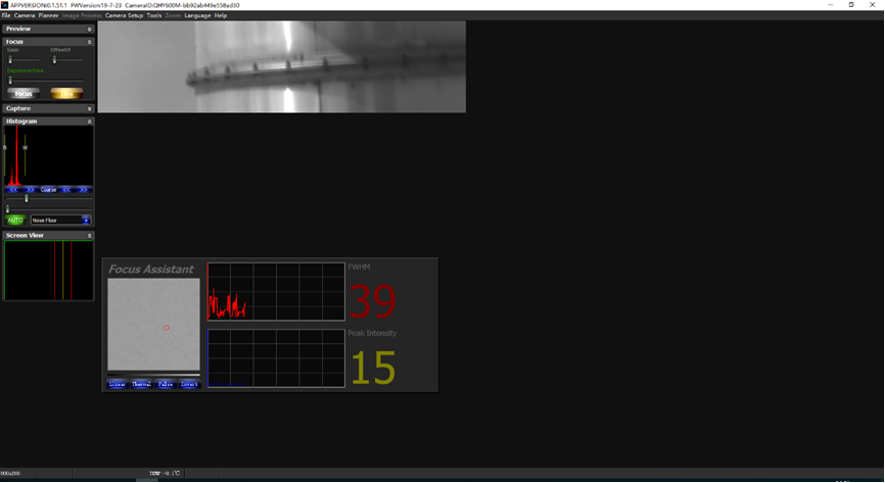
You can use the “preview tab” to preview and use the focus tool to focus. Then use the “capture tab” to capture the image.
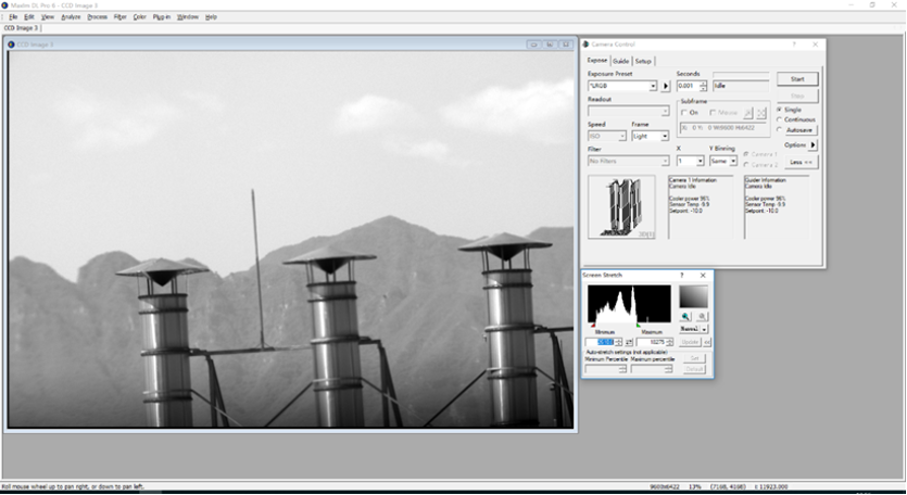
Launch SharpCap. If the software and drivers mentioned above are installed successfully, the video image will appear automatically about 3 seconds after the software loads. You will also see the frame rate in the lower left corner of the software window as shown below.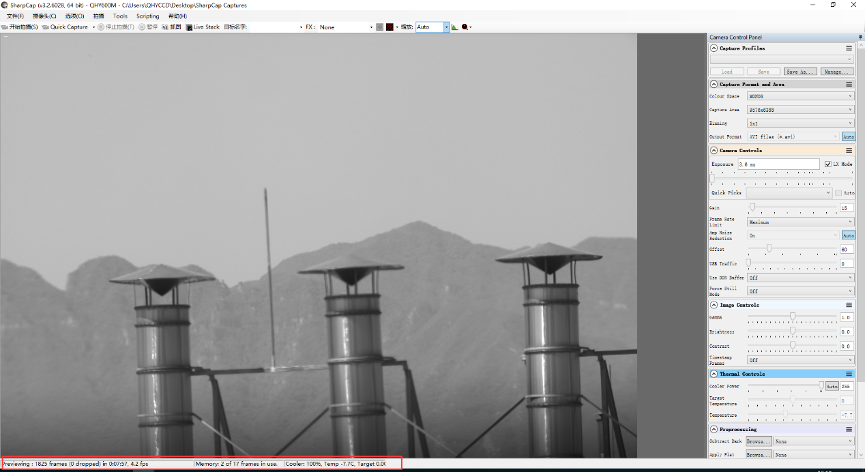
If you have already started the SharpCap software before connecting the camera, in order to open the camera, click on the “camera” in the menu bar and then select the device.
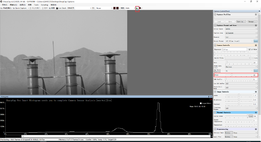
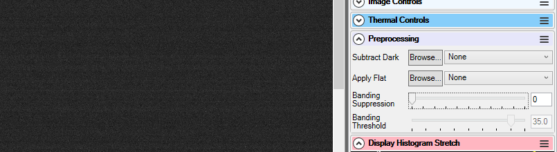
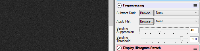
Offset adjustment. When you completely block the camera (i.e., like taking a dark frame) you may find that the image is not really zero. Sometimes this will reduce the quality of the image contrast. You can get a better dark field by adjusting the offset. You can confirm this by opening the histogram as indicated in the figure below.
If you want to enter the 16-bit image mode, select the “RAW16” mode.
By selecting the “LX” mode you can expand the exposure setting range and take long exposures.
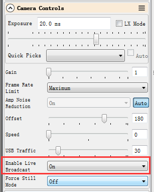
After cooling devices connected to the 12V power supply, the temperature control circuit will be activated. You can control the CMOS temperature by adjusting the settings in the figure below. Basically, you can control the temperature of CMOS by either adjusting “Cooler Power” or clicking “Auto” and setting “Target Temperature”. You can also see the CMOS temperature at the lower-left corner of the software window.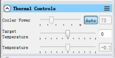
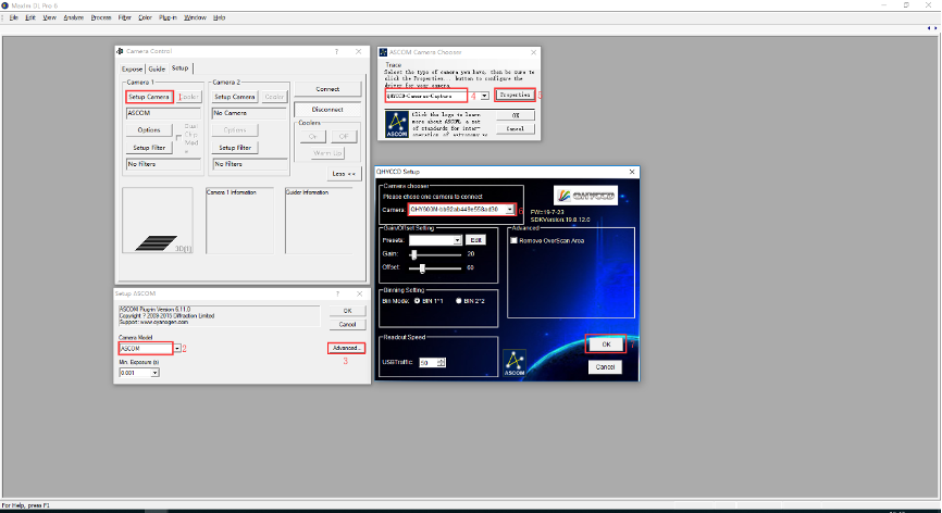
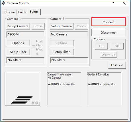
With ASCOM drivers, you can use the device with many software packages that support the ASCOM standard. We will use Maxim DL below as an example, but a similar procedure is used for The SkyX and other software packages supporting ASCOM.
First make sure you have not only loaded the ASCOM drivers but that you have also downloaded and installed the ASCOM platform from ASCOM. After both the drivers and platform are installed, start MAXIMDL. Follow the instructions shown below to finish the setup. Then Click Connect in and enter the software.

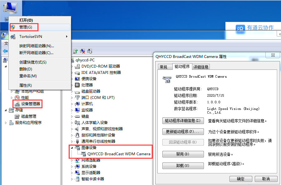
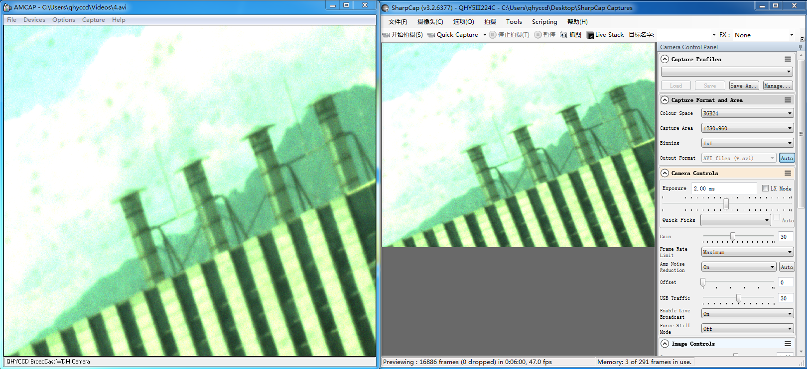
QHYCCD BroadCast WDM Camera is a broadcast driver that supports QHYCCD cameras with video broadcast function, which can meet the needs of customers to send video images to other target software. For example, use sharpcap to connect a WDM-enabled camera, and the sharpcap display video image can be sent to other WDM-supported software for display, which is suitable for video online broadcast applications.
The installation process is over, right-click the computer to find the device manager, and check that the image device name is QHYCCD BroadCast WDM Camera, which means the installation is successful.
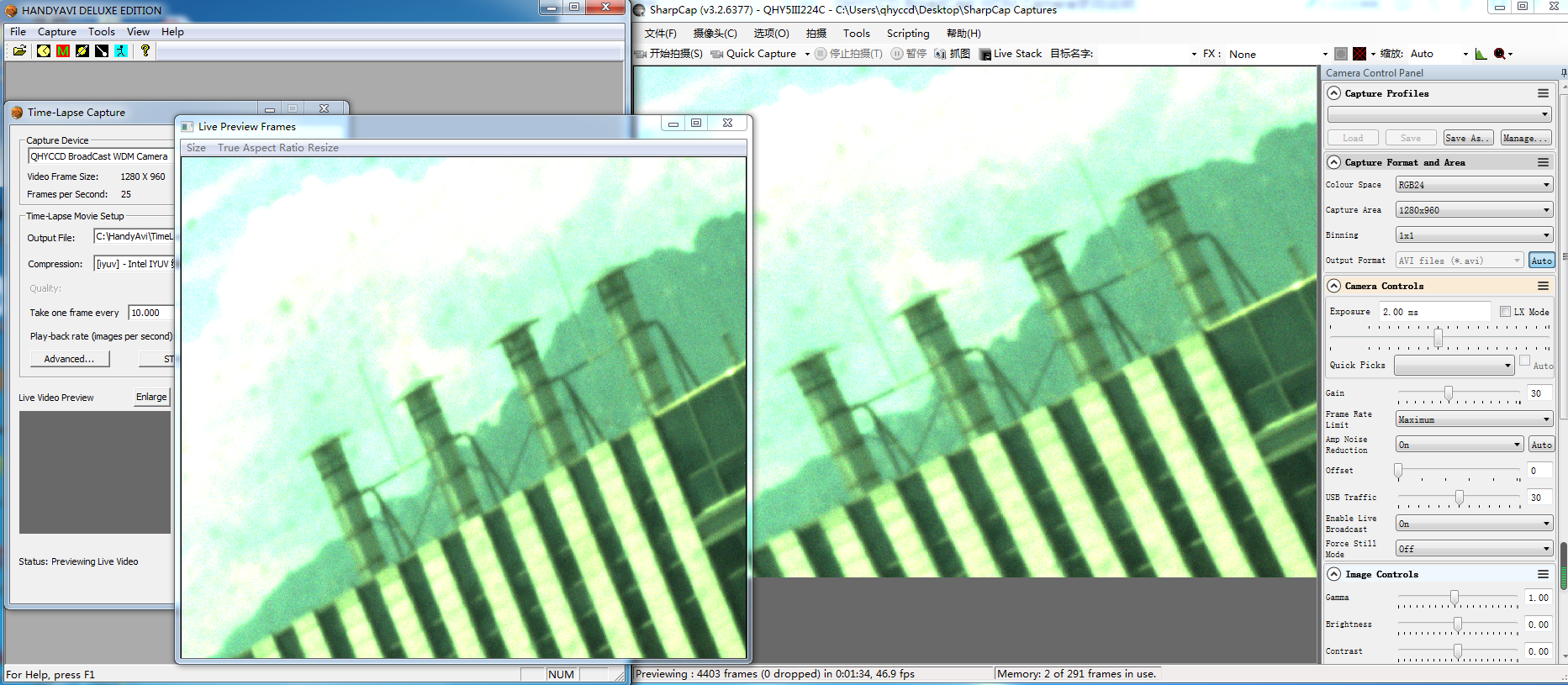
HANDYAVI test effect chart:
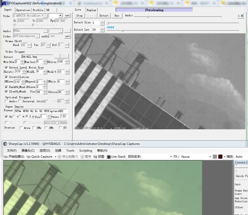
UFOCAPTURE test renderings:
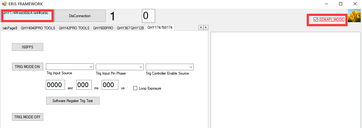
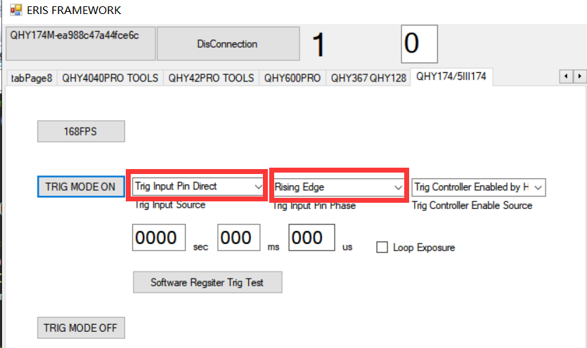
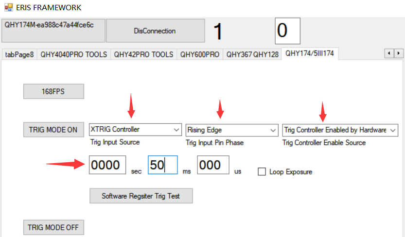
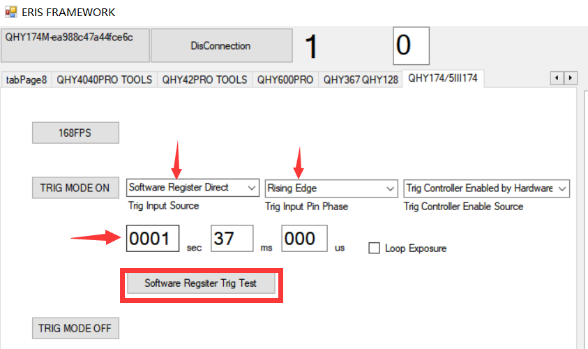
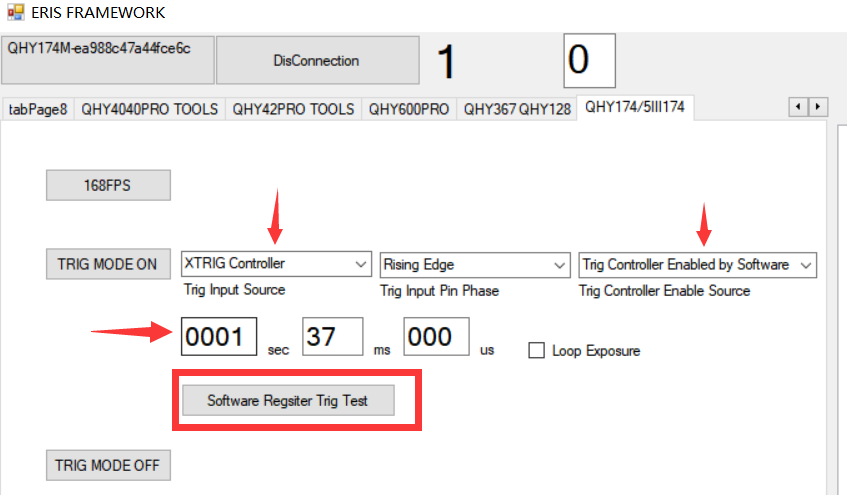
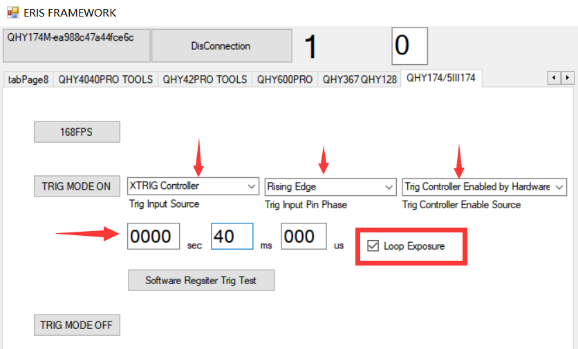
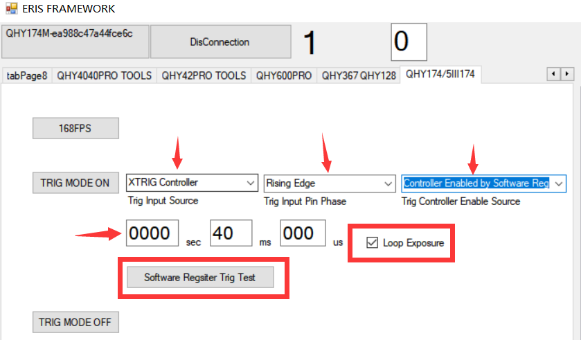
Press the TRIG MODE ON button. You will find that the video image in sharpCAP software stops. The camera has entered a waiting outside trigger state. Trigger the input port via the photoelectric isolation and enter a high level. You’ll find that the image takes a frame, and the longer the duration of the high level, the longer the image will be exposed. In this mode, the exposure time is equal to the duration of the high level.

Buy risk-free: When it’s time to trade up you’ll get the most value for your used gear.